The wind loads will vary in the corners perimeter and field of the roof. EXAMPLE CALCULATION USING ASCE 7-16.
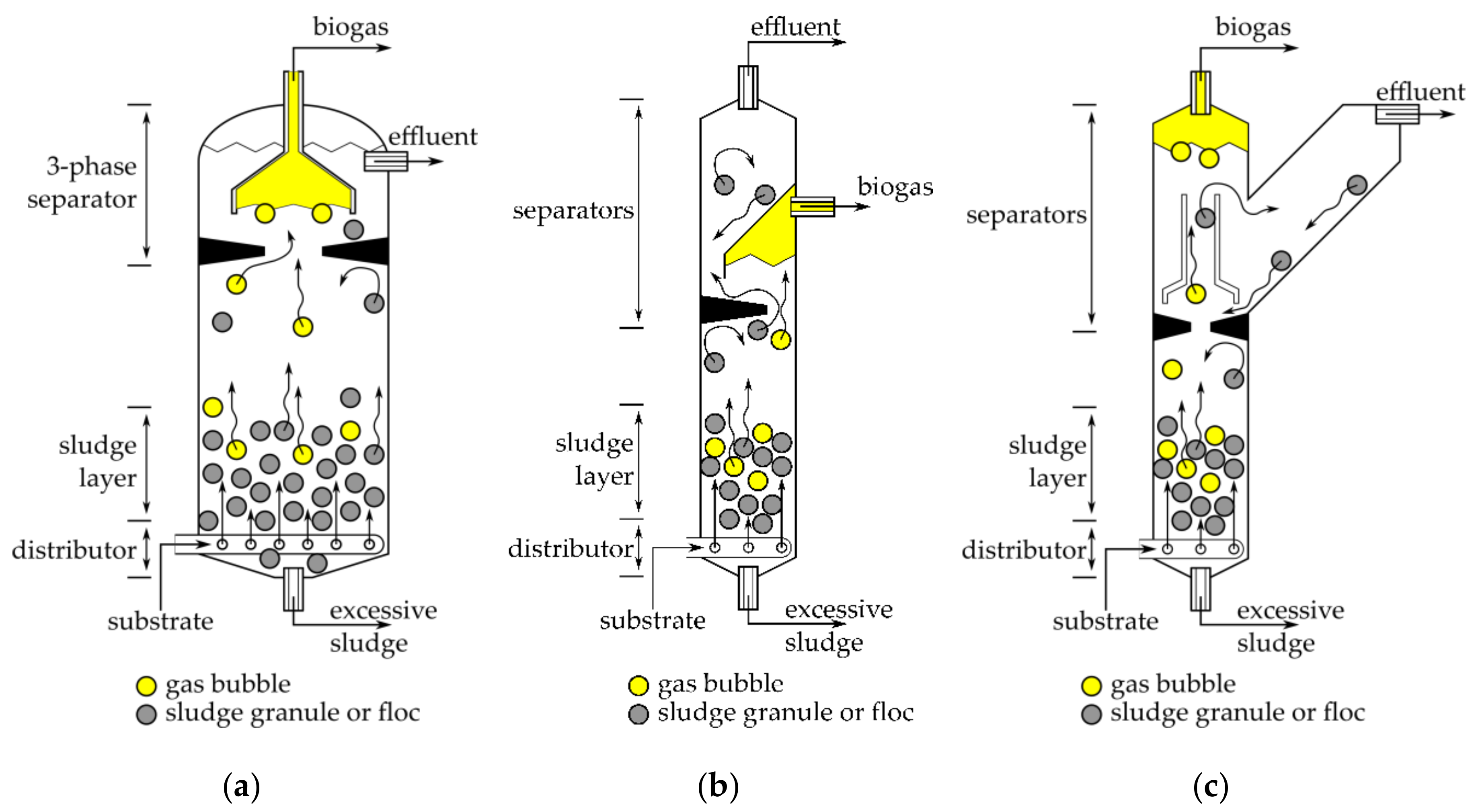
Processes Free Full Text Approaches In Design Of Laboratory Scale Uasb Reactors Html
Wind loads determined per Data Sheet 1-28 are generally approximately 10 greater than those determined by using ASCE 7.
. When the wind design criteria is transferred between designers for the same project specially between the Engineer of Record and Specialty Engineers it is recommended that reference ASCESEI 7. Main wind force resisting system Envelope procedure. The basic design wind speed maps for the continental United States and Alaska remain unchanged and are still based on ASCE7-05.
Determining FM Global De sign Wind Loads. Also FM 1-28 and RoofNavs Ratings. The traditional load factor which accompanies wind is 16 so a combination which includes dead load live load and wind might be 12 Dead 16 Wind 10 Live.
Guide to the Use of the Wind Load Provisions of ASCE 7-02 by. These and other factors are used in conjunction with FM Global Property Loss Prevention Data Sheet 1-28 titled Design Wind Loads to establish the uplift forces on the specific building. The 2002 revision of the FM 1-28 document with a few exceptions adopted the ASCE method.
ASCE 7-02 Minimum Design Loads for Buildings and Other Structures. Outline for determining wind loads from ASCE 7-16. Wind ASD load combination 06W 223 psf.
Metal roof panel suppliers will give you a FM design table for this say 1-105 requires a panel at 5. This document provides the necessary data when read in conjunction with the. FM Approvals or UL.
They incorporate nearly 200 years of property loss experience research and engineering results as well as input from. Under FM 1-28 and also FM 1-31 Metal Roof Systems you need to use a roof panel that meets the FM loadings say 1-105 in the field for example. Calculation of wind loads for low slope roofing.
Roof systems are only Factory Mutual Research-Approved for. Discover the differences in ASCE 7-16s results and those of FM 1-28 ASCE 7 -05 and ASCE 7-10. Look no further than FM Global Property Loss Prevention Data Sheets.
Design Wind Speed is 3-second gust speed at 10m with 50 year return period. Mehta and James M. While data sheet 1-28 will determine the specific size of the corner and perimeter zones data.
Wind resistance Design wind loads. Until 2002 the methods used by ASCE and FM were substantially different. Determine wind loads on structures.
FM 1-28 Code Alert. Per Code Section 6141 the minimum wind load for MWFRS shall not be less than 10 psf. RWD ANSISPRI WD-1 Wind Design Standard Practice for Roofing Assemblies.
In the roofing industry we also often use Factory Mutual. A manufacturing building is located in New Orleans. FM Global is an insurance company and a purveyor of design and installation documents for roof systems eg Loss Prevention Data Sheets 1-28 Wind Design.
1 The basic _____ to determine wind loads can be located in Figure 261-1 of ASCE 7-16 or shown here in Figure 1. However these loads can diverge higher from ASCE 7 if the building is over 60 feet tall or. Wind loads on buildings.
Revised design wind guidance reflects changes in pressure coefficients GC P. FM Wind Rating Specified only. 1-28 to determine wind loads.
WD-1 FM LPDS 1-28 provides a number of look-up charts and tables based on exposure wind speed and roof height which provide design wind loads for the. The following guidelines outline Vulcrafts understanding of two possible approaches that may be taken concerning additional roof deck design requirements FM may require. In this situation the FM Regional Engineer specifies that the roof must have a wind rating such as 1-60 1-75 or 1-90.
The wind loads will vary in the corners perimeter and field of the roof. FM Approvals is a testing facility a third-party certification body and a developer of Approval Standards eg FM 4470 Single-Ply Polymer-Modified Bitumen Sheet Built-Up Roof BUR and Liquid Applied. Building has a roof slope of ½ inch per foot building height of 40 width 100 and length of 200 with no parapet.
These exacting standards help you reduce the chance of property loss due to fire weather conditions and failure of electrical or mechanical equipment. The building is an enclosed. Al ight esevedfWind Design 1-28 FM Global Property Loss Prevention Data Sheets Page 11 224 Topographic Factor Key Topographic effects can increase wind speed locally due to significant his ridges and escarpments of specitied dimensions and proximity tothe building or proposed buiiding in question.
1-28 titled Design Wind Loads to establish the uplift forces on the specific building. The lack of continuity created confusion driving specifiers to rely on. Roof pressures can be determined.
The project must meet the design criteria for the structure outlined in the FM Global Loss Prevention Data Sheet 1-28. FM Global Design Wind Loads are determined by using FM Global Property Loss Preventio n Data Sheets 1-28. These load factors are for strength design.
This data sheet is intended to be used in conjunction with Data Sheet 1-28 Wind Loads to Roof Systems and Roof Deck Securement See FM Global Update Roofing Contractor February 2001. ASCE 7-05 Minimum Design Loads for Buildings and Other Structures. Wind LRFD load combination 10W 372 psf.
Allowable stress design has different load factors Under the new ASCE 7-10 wind specification two things have happened. 45 288 -385 391 -524 Notes. Perhaps the best way to compare the differences in design wind pressures derived from FM 1-28 ASCE 7-05 and ASCE 7-10 is by example.
Design Wind Speed is 3-second gust speed at 10m with 50 year return period. FM Global Property Loss Prevention Data Sheets. Wind Loads by ASCE 7-16 and 7-10 Similar Process.
FM 1-28 now uses pressure coefficients and zone dimensions based on ASCE 7-16 Minimum Design Loads and Associated Criteria for Buildings and Other Structures However FM 1-28 does not use ASCE 7-16s wind maps and basic wind speeds. Instead FM 1-28 uses wind maps and basic wind speeds based on ASCE 7-05. American Society of Civil Engineers 2005.
Loss Prevention Data Sheet 1-28 Wind Design provides the background on the math in calculating the pressures as well as the wind maps. This may be all that. FM LPDS 1-28 Roof Wind Designer from MRCA NERCA and NRCA.
Wind LRFD load combination 16W 350 psf. Items covered include roof covers insulation vapor retarders fasteners and recover assemblies. FM Global Loss Prevention Data Sheet 1-28 Wind Loads.
FM Globals Property Loss Prevention Data Sheet 1-28 Wind Design FM 1-28 includes the following example design wind pressure determination. Wind pressure tables have been removed.

Tu 20 Fm Take Up Ball Bearing Units Skf

Understanding Wind Resistant Design Professional Roofing Magazine

Tu 20 Fm Take Up Ball Bearing Units Skf
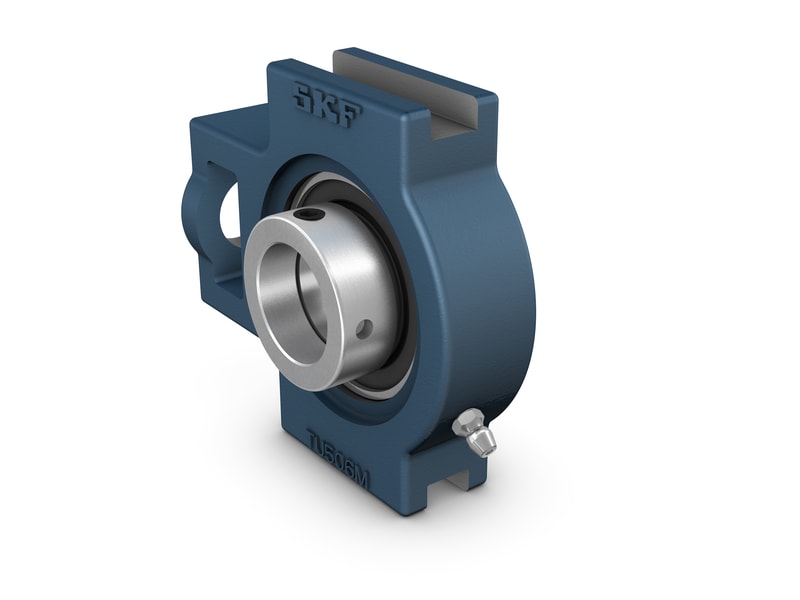
Tu 20 Fm Take Up Ball Bearing Units Skf

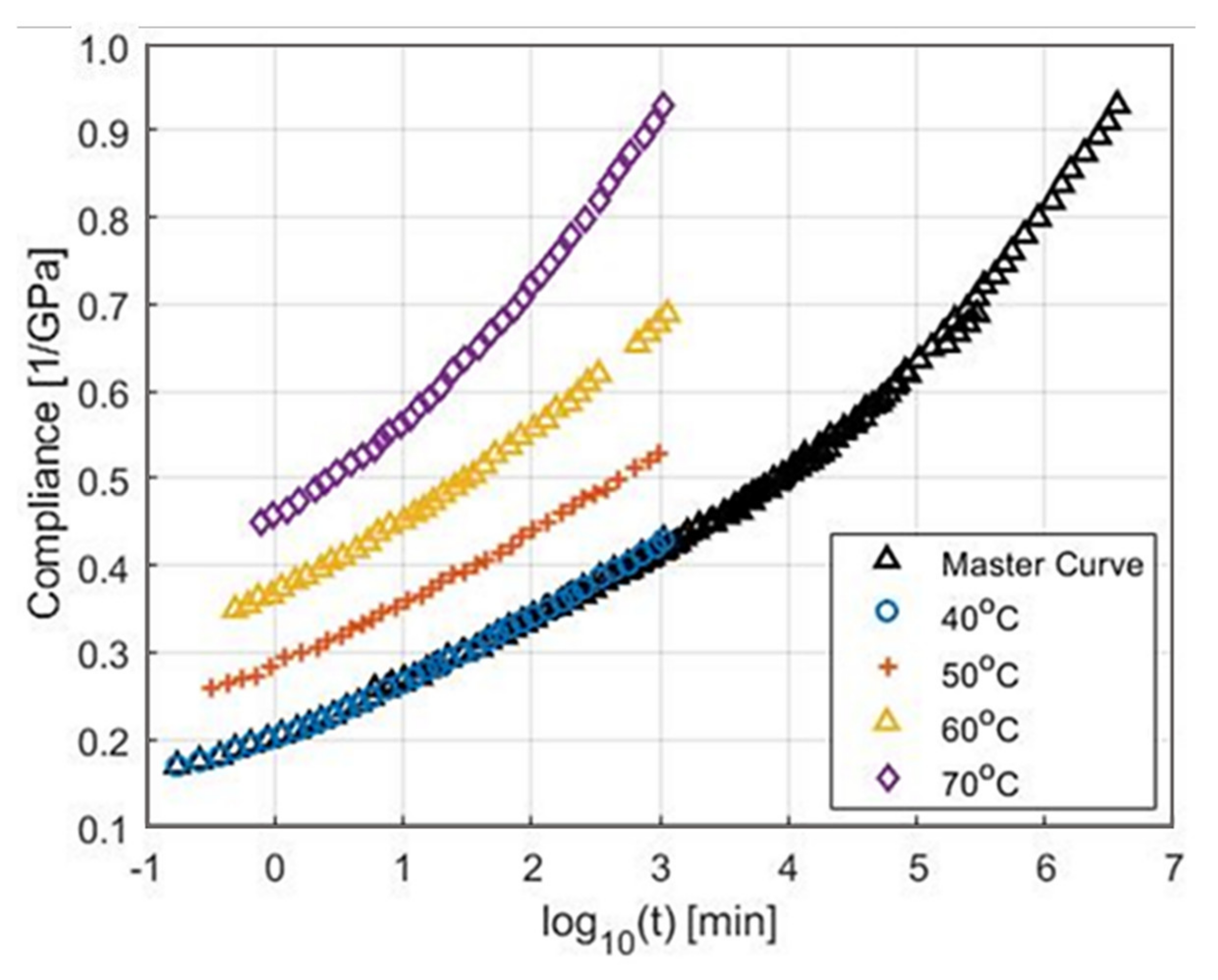
Development Of Vulnerability Curves Of Buildings To Windstorms Using Insurance Data An Empirical Study In South Korea Sciencedirect
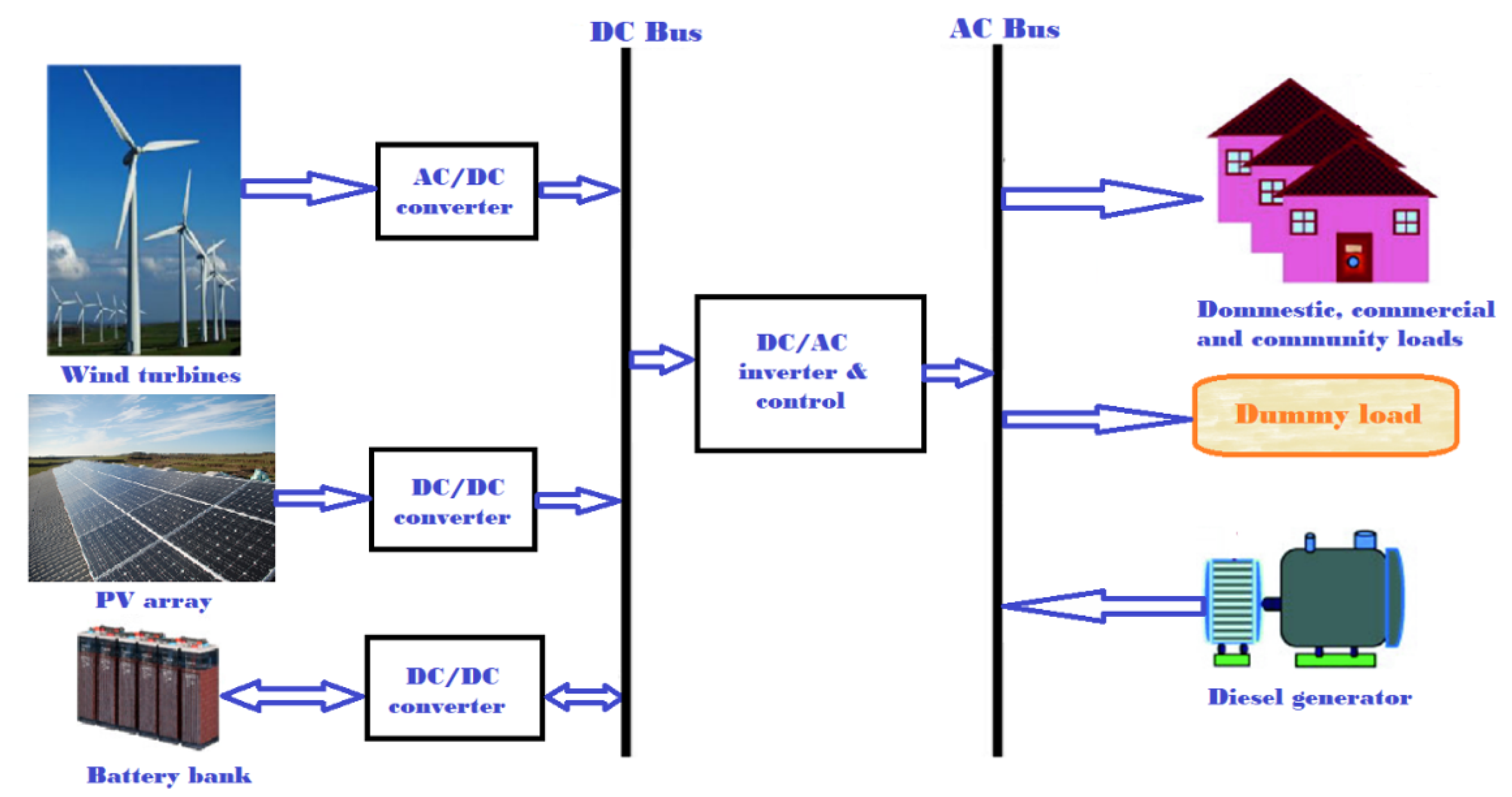
Processes Free Full Text Optimal Sizing And Techno Economic Analysis Of Hybrid Renewable Energy Systems A Case Study Of A Photovoltaic Wind Battery Diesel System In Fanisau Northern Nigeria Html
Encyclopedia Free Full Text Energy Storage Flywheel Rotors Mdash Mechanical Design Html

Understanding Wind Resistant Design Professional Roofing Magazine
0 comments
Post a Comment